


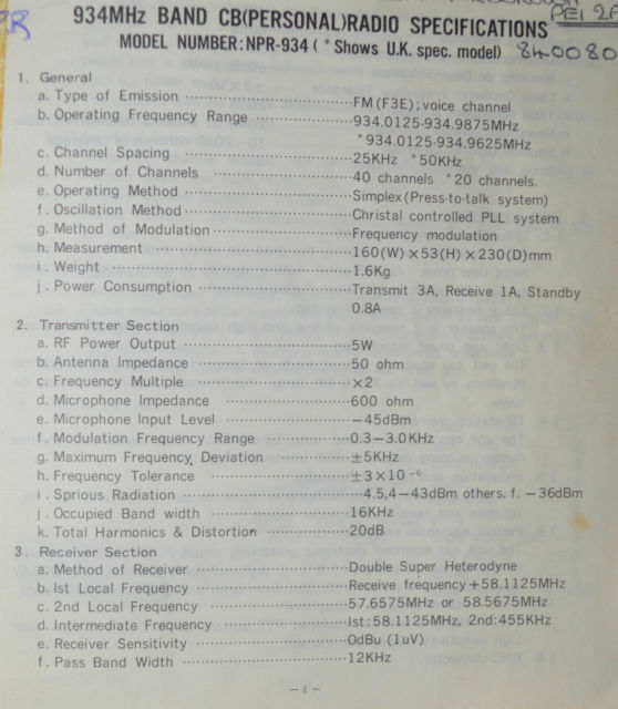
934MHz BAND SPECIFICATIONS
MODEL NPR934• (Shows U.K. spec. model)
- General.
a.Type of Emission …………………… FM (F3E); Voice channel.
b.Operating Frequency Range …………… 934.0125-934.9875 mhz.
*934.0125-934.9625 mhz.
c.Channel Spacing ……………………. 25khz *50khz.
d.Number of Channels …………………. 40channels *20 channels.
e.Operating Method …………………… Simplex (PTT system).
f.Oscillation Method …………………. Crystal controlled PLL.
g.Method of Modulation ……………….. Frequency Modulation.
h.Measurements ………………………. 160(w)x53(h)x230(d).
i.Weight ……………………………. 1.6kg.
j.Power Consumption ………………….. TX-3A. Rx-1A.Standby-0.8A.
2.Transmitter section.
a.RFPower output …………………….. 5 Watts.
b.Antenna Impedance ………………….. 50 Ohms.
c.Frequency Multiple …………………. X2
d.Microphone Impedance ……………….. 800 Ohms.
e.Microphone Input level ……………… -45dBm.
f.Modulation Frequency Range ………….. 0.3-3.0Khz.
g.Maximum Frequency Deviation …………. +/-5Khz.
h.Frequency Tolerance ………………… +/-3×10-6.
i.Spurious Radiation …………………. 4.5,4dBm. Others.f.-36dBm.
j.Occupied Bandwidth …………………. 16Khz.
k.Total Harmonics and distortion ………. 20dB.
3.Receiver Section.
a.Method of Receiver …………………. Double Superheterodyne.
b.1st Local Frequency ………………… Receive freq +58.1125Mhz.
c.2nd Local Frequency ………………… 57.6575Mhz or 58.5675Mhz.
d.Intermediate Frequency ……………… 1st:58.1125Mhz 2nd:455Khz.
e.Receiver Sensitivity ……………….. 0dBu (1uV).
f.Pass Bandwidth …………………….. 12Khz.
g.Attennuation ………………………. 30Khz.
h.Spurious Response ………………….. 60dB.
i.Intermodulation Characteristics ……… 60dBu.(1uV).
j.Blocking or desensitisation …………. 60dBu.(1uV).
k.Local Oscillator Frequency Tolerance …. +/-3×10-6.
l.Total Harmonics and Distortion ………. 20dB.
m.Unwanted Spurious Emission ………….. 20mw at Ant/Terminal-47dBm.
n.Squelch Control Coverage ……………. 10-20dB continuous.
1- Key Features.
1.1. Illuminated operation Panel.
Front operation panel is designed for safety even under night driving. Also Channel number display is being made green which is the most readable colour.
1.2. Easily audible 2 speaker system.
The speakers are of high and low frequency for clear audio sound.
1.3. The unit is equipped with various kinds of lamps to identify the operating condition as well as Tx and Rx lamps. Furthermore electronic sounds do the same.
1.4.10 Station memory.
The unit can memorise up to 10 channels, the memorised channel numbers being displayed with one touch operation.
1.5. Installation and removal flexibility.
The unit is designed for easy transfer from home to car or vice versa via simple installation and removal with the slider mount.
1.6. Perfect electronic circuitry.
The unit is equipped with electronic protection against polarity reversal of DC power, High voltage protection from DC 24volt input and final transistor protection from open or short antenna circuit.
1.7. Multi Function compact Microphone.
The microphone unit is equipped with PTT and UP/DOWN buttons and a high sensitivity microphone element.
1.8. BNC connector.
The BNC connector used is small and light weight for high technology equipment.
Also as connector and cable connections are free from any movement a good connection without power loss is always assured.
1.9. Back up power supply.
The memory can store information for approx 1 week even with the power supply removed or the unit removed from a vehicle.
1.10. Scroll function.
Memorised channel numbers can be displayed sequentially, scrolling in memory and scan modes.
1.11. Channel Number display in Transmit.
During transmit the unit displays channel number at 1 digit steps at 0.5 second intervals.
2.Precautions prior to operation.
2.1. Please check accessory and documents set as described on page 9.
2.2. Please check power supply and antenna connections as described on pages 4-5.
2.3. The unit is designed for use on 12 volt negative grounded polarity.
For 24 volt dc vehicles a suitable DC-DC converter is required.
2.4. Please use a high quality antenna designed for this unit.
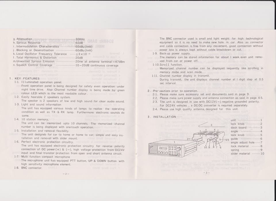
- Installation.
3.1. Mobile Installation.
1) Set the angle to dashborad with 4 screws.
2) Set spring and lock material into slider material.
3) Insert slider and lock material at the unit side and adjust to adequate position.
4) There are 5 holes on the lock material.Set unit at adequate angle and at corresponding position at guide hole. Then turn lock knob clockwise slightly.
5) The unit can be set with +/-15 degrees to +/- 30 degrees with the lock material. Set unit desirable angle and fix the lock screw.
- Important note*
A) Set the unit with care for the lock material position.
B) Use only the supplied screws and parts.
C) It is important to install at suitable position to maintain high performance for long period of time.
Following positions are not suitable so avoid these positions and install in open position as much as possible.
*Place under direct sunlight or direct heat from heater.
*Place away from water ingress and dust, high magnetic fields or vibration.
*Place under unventilated enclosures or areas of heat accumulation.
*Place of direct mechanical shock or vibration.
3.2. Installation for rubber foot and stand material.
It is required to install rubber foot and stand materials when unit is used as a fixed station away from a vehicle.
3.3. Connection of power supply.
Connect DC power cable plug into socket on rear panel.
1) Turn on power switch only when all connections are made.
2) Red cable for +12volts to be connected to power supply for car radio or cigar lighter which must have 5A capacity.
3) Black cable for -12volts to be connected to vehicle ground connection.
4) When you intend to connect to the vehicle fuse box select a terminal that has more than 5A capacity and connect to units red cable(+12volts in).
5) The unit has reverse power protection, in the event of reversed connection the inline fuse in the power cable will blow. Replace the fuse with a 5 A capacity fuse after correcting the connection.
6) The unit has a memory back-up function, maintaining memory for approximately 1 week without a power connection.
7)
3.4. Antenna cable connection.
1)The unit is designed for a BNC connection only.
2) Refer to right figure. Insert antenna plug into antenna connection on rear panel and rotate clockwise approximately 180 degrees until locked.
Once locked the plug should not be able to be pulled from its connector.
3) Keep power off untill all connections are made.
4) When you intend to remove the antenna plug, rotate counterclockwise to release the lock.
3.5. External speaker connection.
When attempting to use an external speaker for clearer sound referring to right figure, connect speaker plug to the speaker jack socket on the rear panel.
You should hear only sounds from the external speaker as the internal speakers are now disconnected so no sound will be heard from the unit.
Use a speaker with 8 or 4 ohm impedance and adjust volume output to 0.5 watt for comfortable listening.
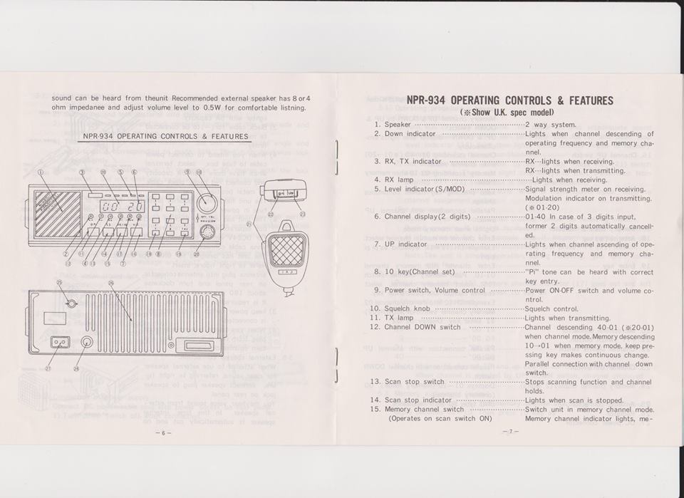
NPR 934 Operating controls & Features.
- Speaker ……………………. 2 way system.
- Down Indicator ……………… Lights when operating frequency and memory channel descends.
- Rx-Tx Indicator …………….. Lights on receive and transmit.
- Rx Lamp ……………………. Lights when receiving.
- Level indicator (S/Mod) ……… Signal strength meter on receiving, Modulation indicator on transmitting (01-20).
- Channel display (2 digits)……. (01-40).In case of 3 digit input former 2 digits automatically cancelled.
- UP indicator ……………….. Lights when frequency or memory channels ascending.
- 10 key (channel set) ………… “Beep” tone heard when key entry is correct.
- Power switch/Volume control ….. Power on/off and volume level.
- Squelch Control ……………. Sets squelch threshold level.
- Tx lamp …………………… Illuminates when transmitting.
- Channel down switch ………… Channel descends (40.01).(*20.01)when in channel mode.In memory mode descends 10-01. Pressing the key repeatedly makes continous change.
Parallel connection with channel down switch. - Scan stop switch …………… Halts scanning function and channel holds.
- Scan stop indicator ………… Lights when scan halted.
- Memory channel switch ………. Switches unit into memory channel (operates on scan switch only) mode.
Memory channel indicator lights, memory channel number (2 digits) is displayed.
Memory channel up/down by up/down switch.
Up/down indicator also lights simultaneously. - Channel UP switch ………….. Channel asscends (01.40).(*01.20)when in channel mode.In memory mode ascends 01-10. Pressing the key repeatedly makes continous change.
Parallel connection with channel down switch. - Memory Channel Indicator ……. Lights in memory mode.
- Asterisk (*) key …………… Enter channel on manual channel select. Eg.Ch 12-12 * (sounds bip bip bipbip.)
- Enter Key …………………. Enter channel into memory channel 01-10. Push memory channel switch(15), select memory channel, select channel number and push enter key. Eg. Channel 12 into memory channel 02.Memory channel switch Up/Down (02)-12 Enter key. Display reads 02-12.
- Microphone connector.
- PTT switch.
- Channel Down switch ………… Parallel connection with channel down switch.
- Channel UP switch ………….. Parallel connection with channel UP switch.
- Memory Channel display ……… Displays 01-10 (memory mode) 00 (2 digits) ordinary channel).
- Antenna connector ………….. BNC type 50 Ohm Impedance.
- Heatsink (radiator).
- DC Power connector.
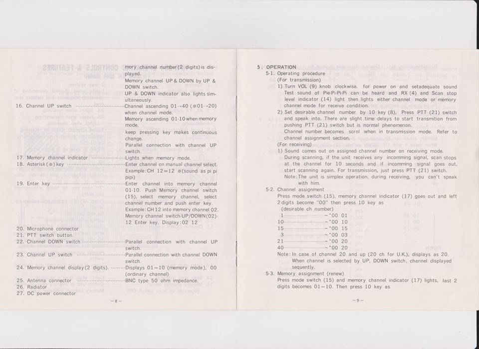
- Operation.
5.1. Operating procedure
(for Transmission.)
1) Turn VOL (9) knob clockwise for power on and set adequate sound.
Test sound of beeps should be heard and RX (4) and Scan stop level Indicator (14) light then lights in either channel mode or memory channel mode for receive condition.
2) Set desirable channel number by 10 key (8). Press PTT (21) switch and speak into the microphone. There are a slight time delays to start the transmission from pushing PTT switch (21) but this is a normal phenomenon.
Channel number scolls when in transmission mode. Refer to channel assignment section.
(For receiving).
1) Sound comes out on assigned channel number on receiving mode.
During scanning if the unit receives any incoming signal, the scan stops at the channel for 10 seconds and if incoming signal stops, scanning starts again. For Transmission just press PTT (21) switch.
Note: The unit is of simplex operation, so during receiving, transmissions wont be heard by the other party.
5.2. Channel assignment.
Press mode switch (15), memory channel indicator (17) extinguishes ann left 2 digits become “0-0” then press 10 key as desirable channel number.
1…………….00-01
10……………00-10
15……………00-15
3…………….00-03
21……………00-20
40……………00-20
Note: In case of channel 20 and up (20 ch for UK), displays as 20 when channel is selected by UP/Down switch, channel is displayed sequentially.
5.3. Memory assignment (renew).
Press mode switch (15) and memory channel indicator (17) lights, last two digits become 01-10. Then press 10 key.
Desirable memory n0. Display. Desirable channel n0. Memorised display.
1—————– 01 ??——1—–(ENT) 01-01
4—————– 04 ??——20—-(ENT) 04-20
10—————- 0 ??——15—-(ENT) 10-15
Memory can be made 1 to 10 even disordered.
5.5. Memory Recall.
To be made in memory mode.
Desirable recall n0. Display.
1—————— 01-01
4—————— 04-20
10—————– 10-15
Memory recall can be made even when memory disordered.
When using UP/Down switch (12) (23) or (16) (22) as
01-01
02-?? (set channel number). UP^
03-??
04-20
- –
- –
10-15
09-??
08-?? Down.v - –
- –
01-01
Note: When holding either Up/Down key for more than 1 second, channel and memory are displayed as scrolling.
5.5. Squelch adjustment.
Squelch function is to eliminate background noise when unit is in stand-by.
If squelch is correctly adjusted then background noise such as static or weak stations cannot be heard.
With squelch (10) turned fully counter clockwise static or other background noise will be heard.
Adjust the control turning clockwise until the noise stops, adjuting as necessary to silence the receiver.
AFTER SALES SERVICE.
6.1. For after sales service consult your local dealer or directly to the address on the guarantee card.
6.2. Guarantee period is stipulated on your gurantee card, refer to it for details.
- ACCESSORY SET.
Microphone………….1Pcs
Power cable…………1Pcs
Mount angle…………1Pcs
” lock knob………2 Pcs
” guide………….2Pcs
” spring…………2Pcs
” Slider material…2Pcs
” lock material…..2Pcs
Angle Mount screw……4Pcs
Rubber Foot ………..2Pcs
Rubber foot and screw..2Pcs
Stand material………1Pcs
” washer…….4Pcs
” ………….2Pcs
Microphone hanger……1Pcs
Fuse (5A)…………..1Pcs
Guarantee card………1Pcs
Operation manual…….1Pcs